Retroradio: reboot
A few years back I’ve turned an old radio into a connected audio device using a Raspberry Pi Model B Rev 2. Recently, I decided it to reboot this project. The goal of this series of posts if to describe how all this working technically, and all I had to learn to make it work (if you are already into electronics, you might skip some paragraphs describing basic concepts).
Back to 2016
At this time my only goal was to have a cheap and standalone system to stream audio from my phone, or to browse the mp3 collection stored on my Synology NAS. I only had a couple of hours to invest on this project, so I did it simple:
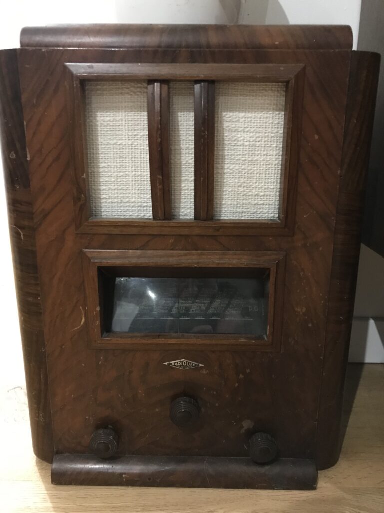
- Use an old wireless radio for the case: I removed the old speaker which was broken, and also changed the fabric hiding it,
- I took apart a cheap computer speaker system and installed the amplifier and the loudspeakers in the case,
- I configured installed Volumio on my Raspberry Pi, and connected the jack audio output.
That’s it, it really took me 2 hours all included. Of course, seen from the inside the result was not that great:
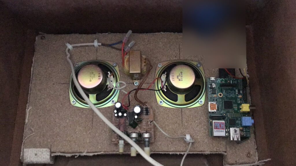
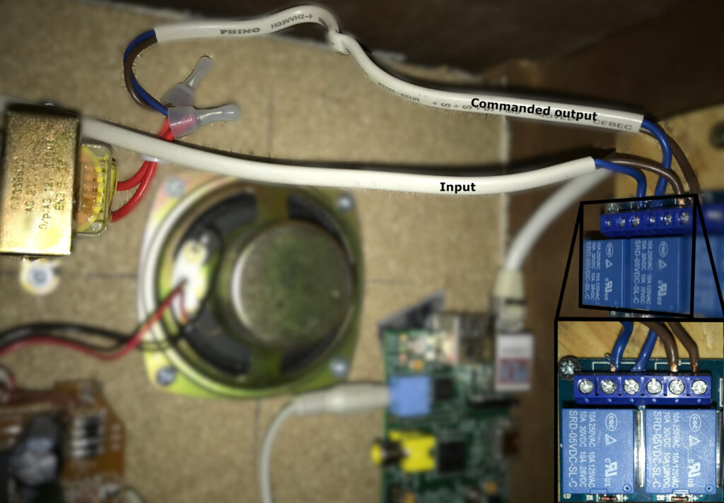
Initial version of the wiring: between the two speakers are positioned the 220v-12v converter (top) and the 12V sound amplifier (bottom). The raspberry pi is powered separately using a 5V usb socket, and audio is outputted using the 3.5 jack connector (not visible in this picture).
Pro
- Nice old-school design, with all the benefits of a modern connected audio system: streaming and sound casting, media library browsing.
Cons
- Electric consumption: I wanted to keep the ability to plug/unplug the amplifier to save power, without having to boot/halt the raspberry pi (which takes time). With this design, it requires two power sockets: one for the sound system, and the other for the RPi,
- The sound quality is limited due to cheap components,
- There is no way to control the amplifier volume, buttons are inside the box and not accessible from the front.
First step: control the amplifier power source
In order to reduce the power consumption at idle state while keeping the system reactive, I decided to keep the RPi always on, and automatically turn on the amplifier power when playing music. Note that, as listed here, the typical power consumption of my RPi is 500mA, and for now it is ok to keep it on (I have several ideas to try to improve this, I leave it for later).
In order to automatically turn on and off the amplifier, we need to use relays driven using the RPi GPIO pins, and activate GPIO automation on volumio.
Relays
A relay is an electrically operated switch (wikipedia): a signal is used to turn the switch either on or off. The main characteristics of a relay are defined by its command and load circuits, which may both vary in term of voltage and current.
First (wrong) try
At first I tried to use one of these Finder 30 series relay (I bought it from a local electronic store, advised by the seller):
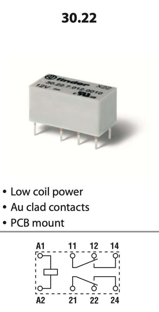
The wiring diagram shown on the left helps to understand how relays work:
- The pins A1 and A2 are connected to a coil: it is an electromagnet that attracts the mechanical switch when powered up.
- The pin 11 (or 21, this relay has two synchronized load circuits) is connected to one side of the switch (let’s call it the input pin),
- The pin 12 (or 22) is in contact with the switch in idle mode, ie. when there is no current between A1 and A2, the circuit between pins 11 and 12 is closed,
- The pin 14 (or 24) is not in contact with the switch in idle mode.
Sending current between A1 and A2 pins moves the switch from 12 (22) to 14 (24).
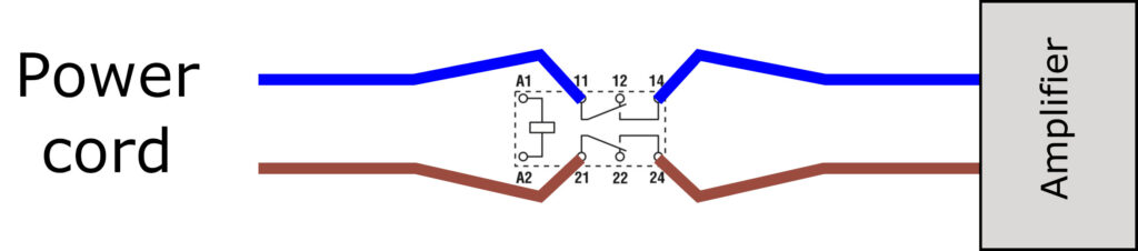
For my project, my plan was to use this relay to open or close the 220v circuit powering the sound amplifier. As the power cord has no ground and can be plugged in two different directions in the wall socket, there is no way to know which cable is the phase or the neutral (electrical switches should be wired on the phase circuit and not neutral). As such, I have found safer to use the two load circuits of the relay and open the two circuits, as shown below:
Unfortunately, after some experiments I discovered that the command coils requires 50mA, while the RPi GPIO (see next sections) pins produce only 16mA: it do not produce enough power to activate the electro-magnet, and thus operate the switch.
The seller was wrong, these relays are not compatible with GPIO. I’ve lost some time, but I learned a lot trying to figure out what was wrong.
Better option: relay board
Instead of using my fancy relay, I went the easy way and bought online a relay board compatible with GPIO current (works with both Arduino and RPi). A very nice feature of these boards is to embed optocouplers, which isolate the command and the load circuits in order to not destroy your command circuit with power surge from the load circuit (see more details here).
In order to have switches on both the neutral and phase lines, I used two relays as shown below:
Driving relays using GPIO
GPIO stands for General Purpose Input/Output. The official documentation (must read before going further) can be found here: raspberrypi.org/documentation/usage/gpio/.
The right video demonstrate the final wiring I managed to design in order to use my relays. As mentioned in the documentation, I started by use the pinout command to know where is physically located each pin, and then used my relay to turn on/off red and green leds with the relays. I followed this process:
- Turn on ssh on volumio (how to),
- Once connected, call the
pinoutcommand, you should get this kind of output:
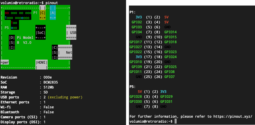
- With my setup, I decided to use:
- pins (2) and (6) to create a 5V power line: it will be plugged to the lights, diverted either to the red or the green LED depending on the relay status (open or closed, respectively).
- pin (11) – GPIO17 to send the command signal to the relay
- pins (1) and (9) to power the relay board.
- To trigger the relay, as visible in the video above, I used the
gpiocommand:gpio -1 mode 11 out
Set the pin (11) to output mode (-1is here to indicate that we use physical pin number for identification).gpio -1 write 11 1
Turn on power on pin (11) (3.3V with something like 16mA): close the relay, green led is turned on.gpio -1 write 11 0
Turn off power on pin (11) : open the relay, red led is turned on.
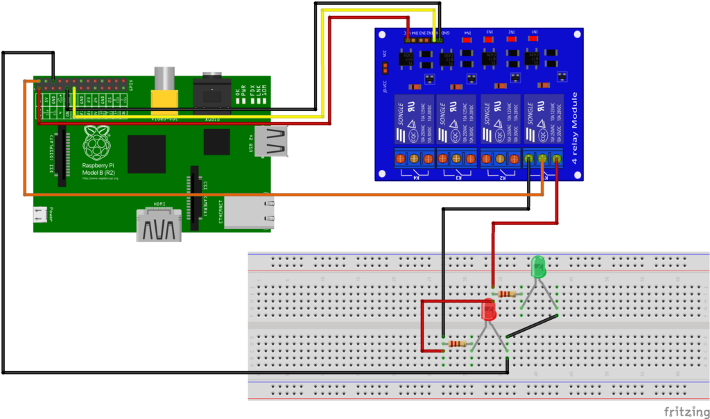
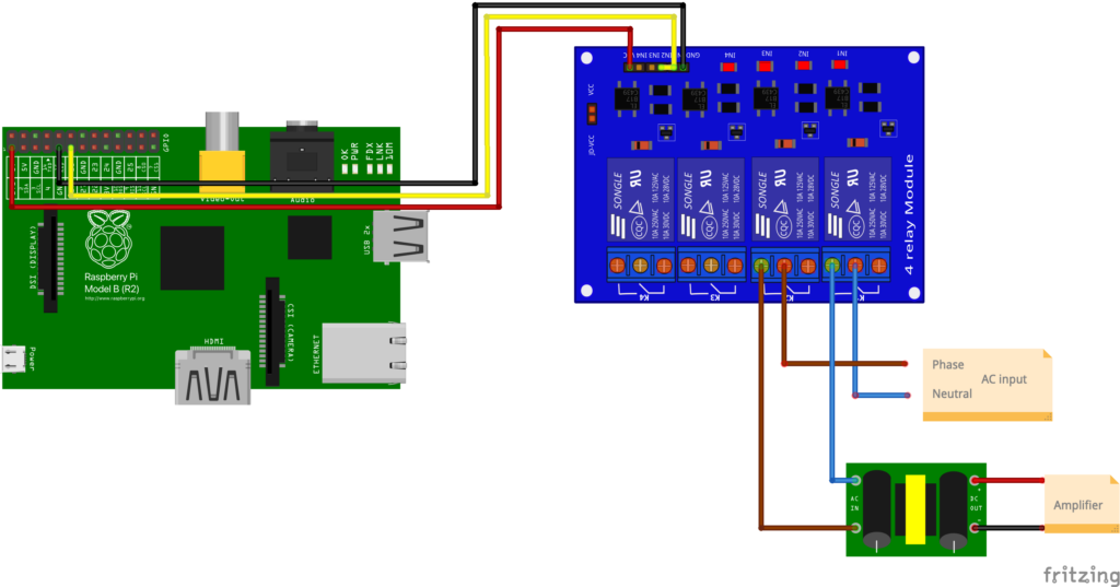
This wiring allows to test the relay board. The final wiring with amplifier is:
Using GPIO with volumio
This step was super easy, I just had to use the plugin gpio-control for volumio, which allows to control GPIO pins when events occur, e.g., play, pause and stop music. My configuration looks like this:
